Model building
Eurofighter Typhoon
www.e-rokodelnica.si
Model building | Eurofighter Typhoon | www.e-rokodelnica.si |
Wikipedia: Eurofighter_Typhoon
Here, it is described how to build a plywood airplane model of Eurofighter Typhoon. The airplane model is a fretsaw project and it is designed to learn sawing with a fretsaw and other skills. Since the model is not difficult to make, it is suitable for beginners. The model airplane is not a flying one, but it can be used as a toy. It has a seat for a pilot. On the carriers under wings, two rubber bands can be strained to make the airplane armed.
| 
| 
|
It is not allowed to use this document or part of it for commercial purposes. The exception is teachers who may use it at their own classes.
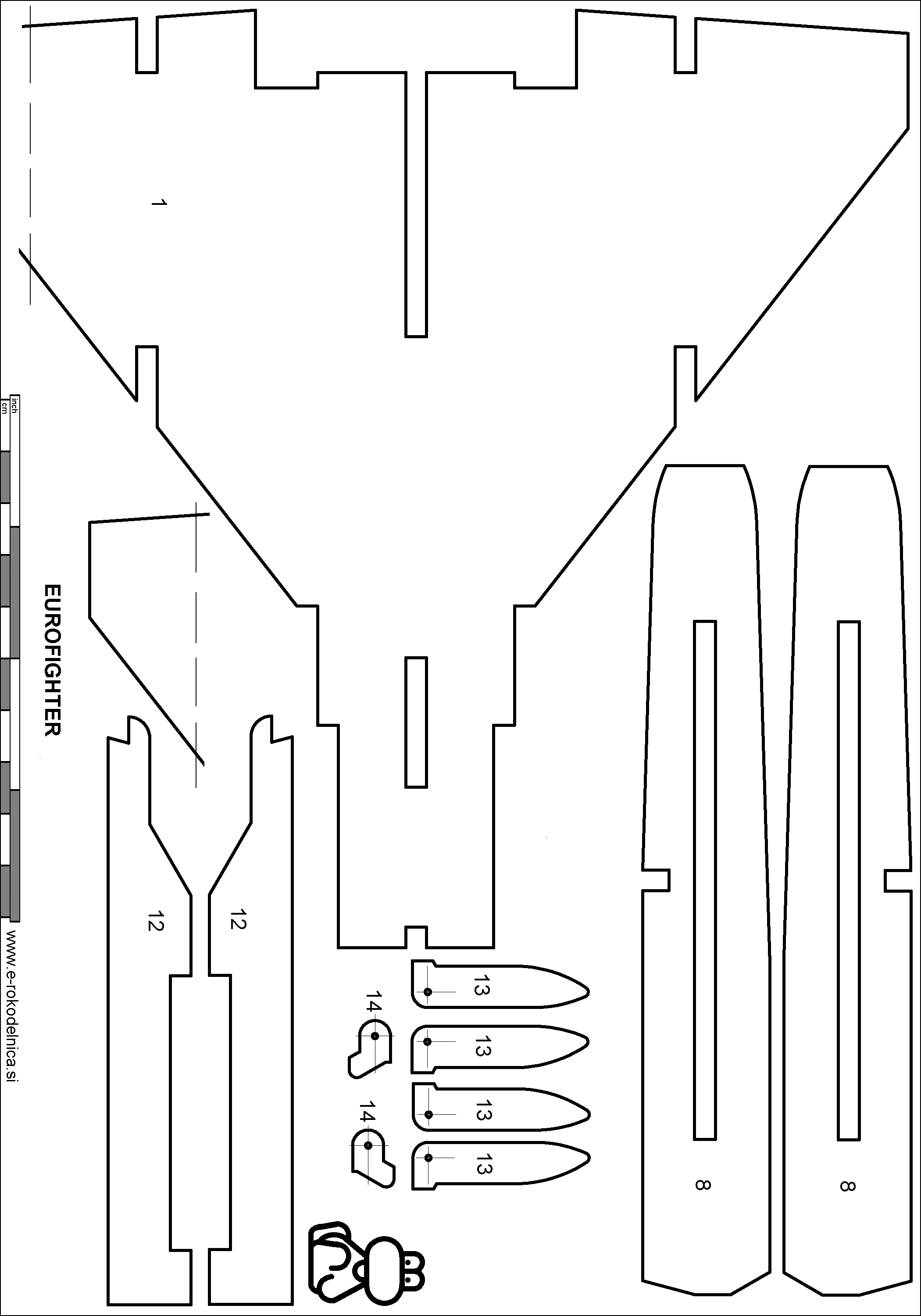
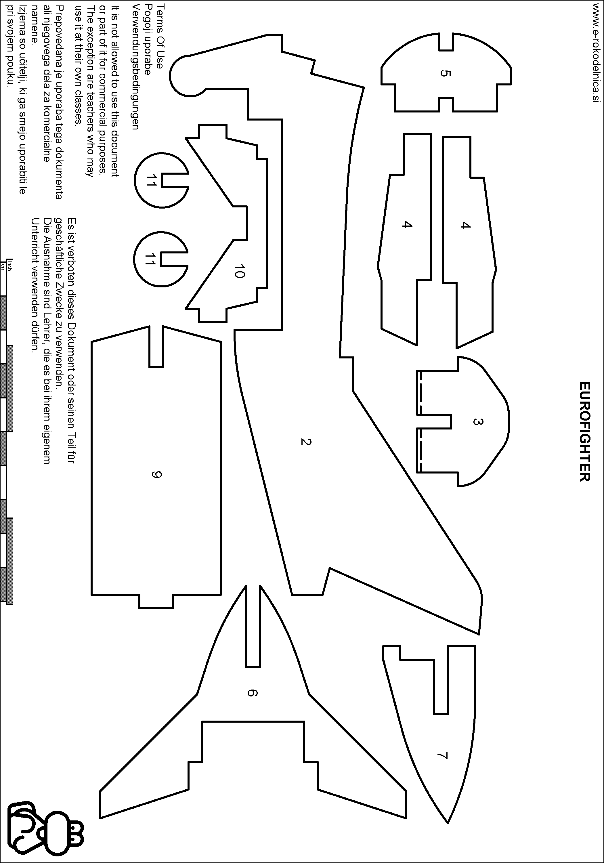
We cut parts of the aircraft out of 4 mm thick plywood first. We find patterns of the parts in files that are pointed at by links in the figure 1. Each part is to be cut once. Parts, which take part in the assembly twice like fuselage sides 4 are also drawn twice in the drawings. The wing 1 is too big for the drawing. So, it is divided to two pieces, which should be joined when the wing is transfered to board. Transfering is described in greater detail in the page Transferring Shapes of Parts to Plywood.
  |
  |
Figure 1: Parts of the Aircraft
Before we cut parts out, we should drill holes in parts 13 and 14. Afterwards, we cut all parts out of plywood as precisely as possible. We can find some tips to help us sawing in the page Using of a Fretsaw. Joints must be cut precisely to make assembling easier.
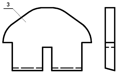
Figure 2: Sanding of bottom edge of seat backrest 3
After that, we sand the parts to remove cutting marks. The bottom edge of seat backrest 3 should be sanded to an angle as it is shown on the figure 2.
We glue the parts together.
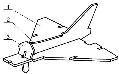
Figure 3: Assembly of wings and hull, Step 1
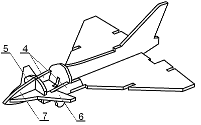
Figure 4: Assembly of cockpit, Step 2
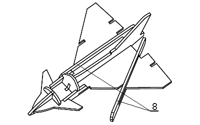
Figure 5: Engines, Step 3
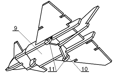
Figure 6: Undercarrige, Step 4
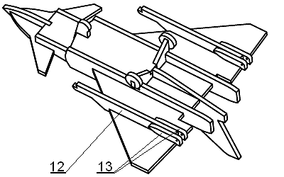
Figure 7: Ordnance hardpoints, Step 5
The plane is prepared for sanding and painting. The triggers 14 are sanded thinner so that the two can rotate smoothly when they are attached to parts 13.
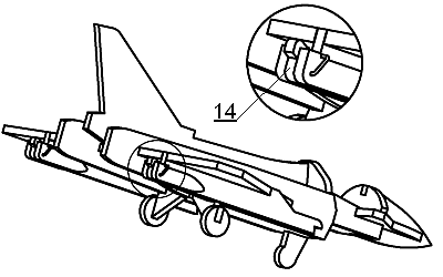
Figure 8: Auslöser, Trigger, Step 6
The triggers 14 are attached to the ordnance hardpoints by wire as it is shown on the figure 8.