Model Building
Biplane

www.e-rokodelnica.si
 Model Building | Biplane |  www.e-rokodelnica.si |
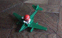
This page describes a model of a biplane made of plywood that has a propeller driven by an electric motor. The airplane model is designed to learn sawing with a fretsaw and other skills. The biplane is not a flying one, but it can be used as a toy. Because of small parts, it (as a toy) is not suitable for children under three years.

| 
| 
|
It is not allowed to use this document or part of it for commercial purposes. The exception is teachers who may use it at their own classes.


 |
We cut parts of the biplane out of 4 mm thick plywood first. We find patterns of the parts in files that are pointed at by links in figure 1. We print the drawings and transfer the patterns to the plywood. A procedure is described in greater detail in the page Transferring Shapes of Parts to Plywood.
  |
  |
Figure 1: Parts of the Aircraft
In the drawings, each pattern is drawn only once. It is written in brackets, how many parts of each pattern we need to cut out. We need two fuselage sides 2, two pillars 9... We transfer them to the plywood board
We cut all parts out of plywood as precisely as possible. We can find some tips to help us sawing in the page Using of a Fretsaw.
We sand edges of the cut parts with abrasive paper. By sanding, we make also a slant of 15° on the seat back 5 and seat 4, as seen in Figures 2 and 3.

Figure 2: Preparation of the seat back 5

Figure 3: Preparation of the seat 4 (The seat is turned bottom side up)
A hole A for M3 screw is drilled in the seat 4. To make a hole, we need a 3.2 mm drill bit. As seen in Figure 3, we have to make a chamfer the upper side of hole to hide the screw head. When the seat 4 is made, we check the position of the screw and battery holder, as we can see on the figure 4. If we are satisfied with the seat, we store the battery holder and screw until further.

Figure 4: Position of the battery holder under the seat 4 (The seat is turned correctly)
We have to cut two fuselage sides 2. To the one of them, we drill a hole C for a switch. The diameter of drill bit depends on the thread on the switch. Afterwards, we store the switch until further

Figure 5: Position of switch on the fuselage side 2
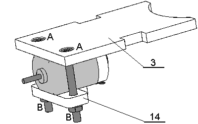
An electric motor is fixed between the hood 3 and holder 14 by M3 screws. In the hood 3, we have to drill two holes A with a chamfer for screw head. Holes B in the holder are made with the same drill bit. Only, these holes B are without chamfer.

Figure 6: Motor assembly
A hole B is drilled also in the battery cover 16.
We have to drill a hole E for wheels in the fuselage sides 2. The diameter of the hole should be slightly larger than the diameter of wire that we intent to use. If we have a wire with a diameter of 2 mm, we should use a 2.5 mm drill bit. Then, we need to drill holes F in the wheels 15. The hole diameter should be equal to the diameter of the wire. In our case, we take 2 mm drill bit.
A hole G in the propeller would be drilled after the propeller is assembled.
 |
Now, we have the parts prepared to start assembling them. First, we build a cockpit. The fuselage sides 2 are fixed to the wing 1. Between the fuselage sides 2, the seat 4 is inserted. We must take care to turn the seat correctly. That is with screw chamfer turned up. Then, we affix the seat back 5 and hood 3. The hood 3 must also be affixed with hole chamfers turned up.

Figure 7: Assembling of the aircraft

Figure 8: Assembling of the aircraft
In a battery compartment, we affix two spacers 6. The two make a step that would support the battery cover 16.

Figure 9: Assembling of the aircraft
After the glue is cured, we affix the tail 7 and vertical stabilizer 8.

Figure 10: Assembling of the aircraft
The upper wing 10 is affixed to the pillars 9 and fuselage sides 2.

Figure 11: Assembling of the aircraft
We glue parts 11, 12 and 13 to make the propeller. After the glue is cured, we drill a hole G. The hole diameter should be equal to the diameter of the shaft of the engine. Its depth should be slightly less than the length of the shaft. We must be very careful to drill it perpendicular.

Figure 12: Propeller
The gluing is now complete. We sand and paint parts of the biplane.
 |
We glue two washers over the holes E in fuselage sides 2. These two washers would allow wheels to turn easier.

Figure 13: Washer
The battery holder is glued inside the fuselage under the seat 4. It is turned with solder tags toward the front of the airplane. Care must be taken that we can insert the screw through the hole in the seat 4. It must remain enough space for mounting the motor.

Figure 14: Battery holder
After the glue cured, we connect the motor, switch and battery holder according to the schematics in the Figure 15.

Figure 15: Electric circuit
First, we attach the switch through the hole in the fuselage side 2. Then, the motor is fixed by the screws and holder 14.

Figure 16: Assembly of electrical parts
We apply a drop of glue into the hole in the propeller and affix it to the shaft of motor. Between the engine and the screw, there should be a gap of one millimeter. We must be very careful that the glue does not flow into the motor, because then it won't turn anymore! Therefore, the aircraft should be turned with its nose down, while the glue is curing.

Figure 17: Propeller
The wire for wheels axis should be 53 mm long. We grind both ends of the wire to remove sharp edges. Then, we apply a drop of glue into the hole in one wheel and attach it to the axis. The axis with one wheel is inserted through the holes in the fuselage sides 2. Now, the second wheel is glued to the axis.

Figure 18: Landing gears
We insert batteries and fix the battery cover 16.

Figure 19: Battery cover
Now, the biplane is ready to take off.

Figure 20: The biplane
 |