
Signal Processing
Speed and Angle Measurement

www.e-rokodelnica.si
 Signal Processing | Speed and Angle Measurement |  www.e-rokodelnica.si |
Often, speed and rotational angle of shaft must be measured. It exists many different ways of different complexity. Here, an IIR filter is described, that interpolate the speed and rotational angle of shaft from Hall sensor's signal that may be disturbed heavily. To implement the filter, no division or squaring is needed. We need only to add and multiply, which are common operations in digital signal processing in microcontrollers and DSP's.
The method was initially developed as a filter that attenuates disturbances in Hall sensors' signal. Therefore, I call it a filter although the method has evolved into PLL (Phase Locked Loop).

| 
| 
|
Let's say, that we have a rotating shaft to which an angle measurement device is attached. Very often, this angle measurement device consists of Hall sensors. In case of BLDC motor, there are three Hall sensors that are positioned around a magnet. Although a measurement resolution is very low, the solution is cheap. When it is also adequate, everything is OK.

Figure 1: Rotational angle measurement in a BLDC motor with Hall sensors
But sometimes, we need to know the rotational angle of shaft more precisely. This is also a case with BLDC motor, where we want to commutate phases some degrees sooner or later in order to improve efficiency or to play with field weakening, braking or so. A two step solution to this problem is straight forward. First, we need to obtain speed. Inertia of rotating parts is usually high and speed of shaft changes slowly. Therefore, a change in speed between two Hall sensor's switching events is negligible. We measure time period between the two events. The angle between the two events is known with construction. This angle is divided by measured period to obtain rotational speed. The second step is to obtain a rotational angle of shaft at a time instant of question. Let's say that phase voltages are generated by PWM (Pulse Width Modulation). At each PWM period, a rotational angle is calculated so that the next PWM period can be generated. We multiply time elapsed from the last Hall sensors' switching event by measured speed and add the result to the known angle at the switching event. The result is the rotational angle of shaft which we need to check when it is time to commutate motor currents.
(Here I want to emphasize that the story in last paragraph is suitable only for relatively slow motors.)

Figure 2: The two step calculation of rotational angle
The reason that I don't like the two step solution is twofold. Let me explain why.
First, we have a division where a highly variable measurement is a divisor. Such division is a hard task for a fixed point processor because the measurement must be checked so that we don't get an overflow or division by zero error...
Disturbances and glitches are the second reason. This has been a real cause for development of filter for speed and angle measurement. The speed is measured between two switching events. The angle is calculated as a distance from switching event. OK, but what if a switching event is a false one. In a common BLDC motor, there are power leads near leads to Hall sensors and it is not hard for disturbances to enter the Hall sensors' signal. When we have got false data, we must wait till next switching events. This time of ignorance could be quite long, especially at low speed.

Figure 2: A false time period measurement
Someone could argue, that the Hall sensors' signal could be monitored to filter out false switching events. Yes, but the program code for the task would become huge and full of branches very fast. Many branches make testing of code difficult, because we should check each execution path. I don't buy this.
 |
The basic idea of in the article proposed angle measurement method is that the low pass filter smooth out step-like changes of angle that is measured by Hall sensors. A remain is the actual rotating angle of the shaft. The proposed filter is very robust because glitches in Hall sensors' signal pass almost unnoticed. Another property that I like is that there is inherently no branching in the code.

Figure 4: Flow of execution
The Hall sensors' outputs are sampled in every PWM period. Immediately after, the Hall sensors' signal is decoded into angles. An angle variable is an integer variable where we use the whole span of the variable. This way, we can benefit from the overflow of integer numbers. Namely, integer numbers overflow the same way as angles do. The overflow is just a turn around.
The Hall sensor's angle from the Figure 4 is an input to the digital filter in the Figure 5.

Figure 5: Block diagram
An output of the filter is also a full span integer. In the sum point at the input, the two integer variables that represent angles are subtracted. Because the angles are integers, we do not have to care about overflows. That is, we need not to check when the difference is above or under a ±180° range, because that cannot happen. To illustrate, lets subtract 121° from -60°. The result is 179° or -181°. In signed integer notation, a subtraction of 0x56 (121°) from 0xD5 (-60°) would result in overflow. But these integers represent angles. So, the result of 0x7F is correct.
Someone may argue that in case of unsigned integers, the subtraction in the example would not overflow. Yes, but we can find another example easily, where unsigned subtraction would overflow.
The difference of the angles is an error signal, which is amplified and then feed to two integrating cells. The first integrating cell gives us a measured speed. The output of the second integrating cell is a measured angle. The error signal forces the output angle to get in the phase to the input angle. At the same time, the output gets in phase to the rotational angle of motor's shaft. We can see that we have actually got a PLL (Phase Locked Loop).
We see in a figure that we have got two parameters that amplify the error signal. We must set the amplification of error signal so that the filter is stable in the first place. Then, the response of the filter must be slow enough that it can cut the steps of the input angle signal in order to shape a ramp at its output also at the lowest speed. The highest speed is not a problem, when the shaft accelerates from standstill. But, a reset of filter during the highest speed may be tricky. Then the input changes fast, but the output leaves standstill slowly. Therefore, the error signal circles around its full span.
To implement the IIR filter in microcontroller or DSP, a proper length of variables must be chosen!
 |
The transfer function is derived from the block diagram in Figure 5. The diagram is not a canonical one. I mean the one that has parameters in feedback branches. If we put a multiplication in the angle feedback, we would get overflow issues at the summing point! To illustrate, let's multiply 179° by 0.99 and add it to -179° or lets multiply 0° and add it to -2°. We have a 2° difference in both cases, but two different outcomes!
The filter consists of three parts. First, we have the input sum point where we obtain the error signal, which is a difference between the input and output angle. Then the difference is multiplied by filter parameters. In both cases from the beginning of this chapter, we multiply the difference of 2° by parameters that are smaller than one. This way, overflows cannot be an issue.
The last part of the filter is an integrating cascade that is controlled by error signal. In the Figure 5, there are two integrating cells. An output of the first cell is rotational speed. The second cell integrates this speed into the rotating angle.
The block diagram in Figure 5 gives us three equations that we write down now.
|
(1) |
|
(2) |
|
(3) |
These equations are joined together to obtain a transfer function.
|
(4) |
An important role plays position of roots of the transfer function 4. We have got two poles.
|
(5) |
The Equation 5 can be simplified substantially.
|
(6) |
We have also got one zero.
|
(7) |
We have three roots and only two parameters. Therefore, we can place only two of the roots arbitrarily. But, even when we have three parameters available to set the roots, the "Error Signal" requirement would prevent us from freedom to place all the roots arbitrarily.
The filter to be useful for rotating angle measurement, its output must follow input ramp without error after transient is over. To prove this, we derive a transfer function from input to the error signal er. To do this, we use Equations 1, 2 and 3 again.
|
(8) |
We feed a ramp signal to the input of the filter. When the angle ramps, then the shaft rotates at constant speed. The next Equation 9 is a ramp in z - domain.
|
(9) |
We multiply the input ramp with transfer function 8 to get the error signal er.
|
(10) |
|
(11) |
We need to find the value of er after transient is over.
|
(12) |
At constant speed, the error signal er falls to zero after transient is over.
 |
We select filter parameters, which give us the roots of transfer function.
| Parameters | |
| a1 | 0.0025 |
| a2 | 0.1 |
| Roots | |
| z2p | 0.95 (double) |
| zz | 0.975 |
In this case, we get double pole in real axis. The zero lies between the two poles and the point 1. Therefore, it causes the filter to overshoot. In our example, the overshoot is low enough. But, when the filter parameters are set so that overshoot is greater than 100%, then the filter would be useless. In later case, we test the filter with 180° step. The output would overshoot the input for more than 180° (100%). That is, the output would come around and start approaching input again. Finally, the output would rotate faster and faster. But, our example filter overshoots far under 100% and we may proceed.
First, the shaft rotates slowly. It does one turn in 100 sampling periods. We see, that the example filter cannot smooth input angle steps fully. The filter tries to follow these steps. This can be seen also in the speed signal.

Figure 6: Rotational angle (a revolution in 100 samples)

Figure 7: Speed (a revolution in 100 samples)
Next, we increase rotating speed for five times. The input steps are smoothed out and the output is ramp-like now. The measured speed is constant.
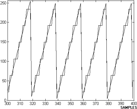
Figure 8: Rotational angle (a revolution in 20 samples)
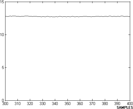
Figure 9: Speed (a revolution in 20 samples)
The diagrams has showed stationary state. But, transient is interesting also. In next Figure 10 and 11, we can see, how the output has cached the input.

Figure 10: Rotational angle (a reset of the filter)
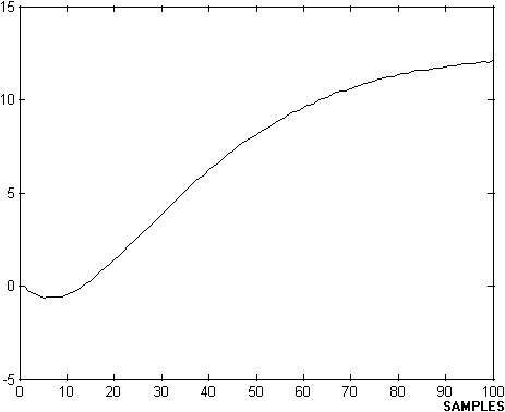
Figure 11: Speed (a reset of the filter)
In the next two Figures 12 and 13, we increase the speed of shaft further. We can see that the output hasn't cached the input in the first attempt. The filter accelerates slowly and it would catch the input once.

Figure 12: Rotational angle (transient at very high speed)
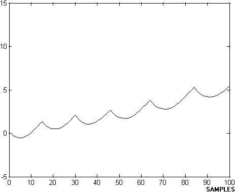
Figure 13: Speed (transient at very high speed)
When the error signal remains inside ±180° range, the filter is linear. But in the later case, the filter falls out of linearity. Therefore, the filter must be examined before we implement it.
In the beginning of the article, I mentioned the robustness of the filter. In the next two figures, we add disturbances to the input Hall sensor's signal. The output signal is still ramp-like.

Figure 14: Rotational angle (disturbance)
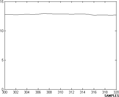
Figure 15: Speed (disturbance)
 |
There are many ways to measure rotational speed and angle from time measurement to Kalman filter. Now, this filter is additional possibility in bag of tricks.