Electrotechnics
CMOS Oscillating Circuits
www.e-rokodelnica.si
Electrotechnics | CMOS Oscillating Circuits | www.e-rokodelnica.si |
Despite their venerable years, the CMOS gates are very handy. They could be used to build very simple and cheap oscillating circuits that are presented here. It is shown how to calculate frequency. Once upon a time, a java script calculator was here to help obtaining a period of oscillations. Unfortunatelly, it is not operational anymore.
| TOC: | ||
 One Gate Oscillator |
 Double RC Oscillator |
|

| 
| 
|
The simplest oscillating circuit could be build around an inverting buffer with Schmitt trigger input. This input is used to lower buffer's sensitivity to disturbances. Especially in case of an input signal that has a very slow slew rate. Then, we would get many switching events near the switching point of circuit which has no Schmitt trigger input.
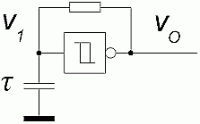
Figure 1.1: Schematics
As we can see in the Figure 1.2, the buffer input oscillates between both threshold voltages VL and VH of Schmitt trigger input. Actually, this hysteresis makes oscillating possible.
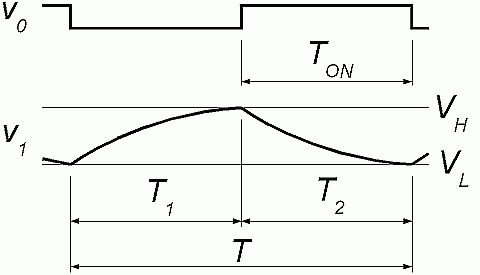
Figure 1.2: Signals
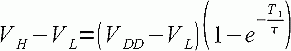
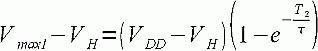
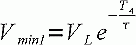
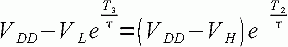
To get a period T, we must figure out rise and fall times of capacitor voltage. First, we calculate rise time T1 from lower threshold VL to upper threshold VH. The time depends on threshold voltages and time constant of RC circuit. The equation is one of the basic equations in electronics.
|
(1.1) |
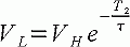
Similarly, we obtain fall time T2 of voltage from upper threshold VH to lower threshold VL.
|
(1.2) |
Now, both times T1 and T2 are added to obtain a period of oscillations.
The oscillator is very cheap and reliable. But, it is extremely sensitive to threshold voltages VL and VH. Different voltages give very different periods and also duty cycles. Unfortunately, these voltages could be very different among devices, especially when we got them from different vendors.
Do not use this circuit when frequency or duty cycle is important!
This oscillator circuit consists of three inverter buffers and two equal RC stages. The frequency is still very sensitive to threshold voltages VL, VH and may vary a lot. But its duty cycle is much more stable.
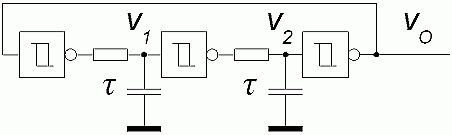
Figure 2.1: Schematics
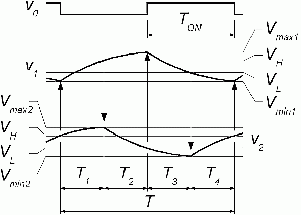
Figure 2.2: Signals
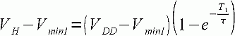
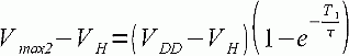
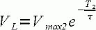
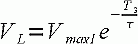
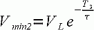
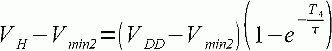
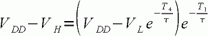
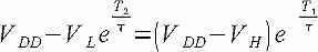
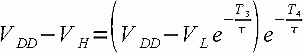
As we can see from the signal diagrams, voltages at gate inputs pass beyond the threshold voltages. We got four peak voltages that are unknown at a moment. Additionally, we got four unknown time periods. To solve for time periods, we need eight Equations form 2.1 to 2.8. These Equations are equations of charging and discharging of capacitors.
|
(2.1) |
|
(2.2) |
|
(2.3) |
|
(2.4) |
|
(2.5) |
|
(2.6) |
|
(2.7) |
|
(2.8) |
The equations are rearranged to cancel unknown voltages out. Here are four Equations from 2.9 to 2.12 left.
|
(2.9) |
|
(2.10) |
|
(2.11) |
|
(2.12) |
Now, some tedious work is to be done to turn these equations around to get time periods. That is, we finish with a quadratic equation, which can be solved to get four exponentials. The logarithm of RC time constant give us periods T1, T2, T3, and T4. Finally, a period T that is frequency can be obtained.
This circuit may be used in case when a stable 50% duty cycle is important. But on the other hand, frequency may vary substantionally.